Author Archives: mirek

Li-Ion spot welder

Almost two years ago I decided to build spot welder for batteries. After researching my options I choose construction by Albert van Dalen

https://www.avdweb.nl/popular/spotwelder/spot-welder-controller-building-kit

It is microwave transformer based, controlled by arduino. It switches primary side with two big-ass thyristors. It also does peak detection of sine wave, to turn on welding exactly when phase voltage is highest. It uses double pulse method. Read his article. I think this is best free construction you can build.

I bought Sunkko welding tweezers. But those are crap. I dissembled them and created two independent swing arms. Arms are long enough for very big battery. Pushing force is adjusted by hand. There is a pedal input to keep both hands for welding.

I measured current trough secondary side with Rogowski probe. It was not during welding, but output was connected firmly together. Over 1200A, nice 🙂

And here is some examples of batteries made with this one:

And this one is done with my spot welder by friend of mine whom I borrowed it.

OpenLRS Tx v1.5

Just another version of OpenLRSng Tx.

  • Open source
  • RFM23BP powered from own adjustable supply
  • Full power of 28.5dBm (700mW).
  • Improved cooling by soldering RFM module to big uninterrupted ground-plane from bottom
  • Atmega328 at 16MHz  powered from 5V, no EEPROM issues as with 3.3V@16MHz
  • True voltage level converters between SPI of RFM and AVR
  • Ready for LCFN-490 filter (with one track cut)
  • Without filter 2nd harmonic at -5dBm, 3rd harmonic -3dBm
  • PPM input buffered and protected (for old radios)
  • Power switch onboard
  • Uses BOARD_TYPE 4 hardware connections
  • Fits in nice aluminum box from Fischer electronics

KOLRSHPTX15 Eagle 6.4.0 files


Dipole antenna with balun

Most of the people are making dipole antennas wrong. Just connecting one pole to center of coax and the other to shield does make poor tri-pole with very distorted radiation pattern. Why tri-pole? Because outer side of shield of coax is carrying RF current and radiates while it should not. On third image you can see poor radiation pattern of dipole without balun.

466px-Dipolefeedradunsymm_englbalun vs pattern

Solution? There are many solutions to solve this. Voltage mode balun, current mode balun, matched transmission line stubs and so on. But for FPV I like 1:1 current transformer design:

Dipolewidebandbalun

Luckily MACOM ETC1-1-13 is exact part we need. It is small SMD part, cheap and easy to get on Aliexpress or eBay. It is rated for max 250mW and up to 3GHz.


etc1-1-13etc1_app_diag

With this information in mind, I have drawn very simple PCB design and milled it on CNC router. Not really knowing if I want it for solder-on SMA connector or direct coax attachment I have designed both and some variations of mechanics. Antennas can be made to any frequency needed, just use longer or shorter poles.

antenna-T

Solder poles and coax

dipole1

Wrap poles together with PCB by strong sewing thread and wick with thin CA. Super strong and poles should not broke off.

dipole2

Another method is to solder SMA made for RG-174 directly instead of coax. Wrapping method applies to SMA too.

dipole3

When everything is soldered and fixed, tuning begins. Put antenna on analyzer and cut off poles by few mm at time on both sides. Frequency starts to shift high and when it is where you want stop cutting. That’s it. SWR 1.4 at 433MHz is what is expected. Dipole is naturally 73ohm plus some reactance, and this type of balun is does not match impedance. It just stops common mode current. So mismatch from 75ohm to 50ohm is still there. But it can be neglected.

IMG_20180103_231451IMG_20180103_231456


And finally this is ready for first flight on my old school test rig. Right is 433MHz for telemetry radio and left is 868MHz for OpenLRSng

IMG_20180107_101526

Eagle files and DXF for milling of antenna cores will be released in few days.

.brd file for Eagle 6.4 

pcb_dipole.dxf


Active Video Splitter with video switch

Out of necessity I designed active video splitter based on THS7314 video amplifier and  TS5A3159A analog switch. Input and outputs are properly terminated by 75ohm resistors and inputs and outputs are AC coupled. For better high frequency response, outputs are coupled with 330uF and 100nF ceramics. Internally it is powered from 3.3V, allowing to run from 5V input. Input channel switch is inverted by transistor to suit my use case.  All components are SMD. Prototype is assembled on CNC milled PCB. Power trough is jump-wired on the bottom side. For future I plan to split design to video switch and video amplifier. Switch will be placed in airplane and controlled via OpenLRS. OpenLRS allows to set pin as switch, instead of servo output, allowing to skip unnecessary MCU to decode servo signal. This prototype will be put in Groundstation where both funcions will be used (switch between live and playback). All components are available trough Farnell.


  • 2 inputs switchable by TTL signal
  • 4 independent outputs
  • Properly terminated inputs and outputs
  • AC coupled inputs and outputs
  • High end video amplifier
  • Solid state analog switch
  • 4V to 15V input power


sch

WP_20170524_21_25_56_ProWP_20170524_21_26_03_ProWP_20170524_21_26_11_Pro


EDIT:

You can download design files here. But beware there is an error. Emitter of PNP transistor shall be connected to 3V3, not VCC.

videoampswitch

Prototype of PPM<>RS485 converter finished

Just first photos of my new invention, PPM<>RS485 bidirectional converter. Both units are same, direction is set by jumper. My goal is obvious, permanent installation of OpenLRS TX module on the roof and UTP cabling. Theoretical distance of transmission if over 1km. First test on 3m UTP works even power is coming through. More info later.

PA120076PA120078PA120080

Antenna tracker


IMG_0273

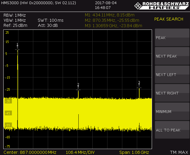
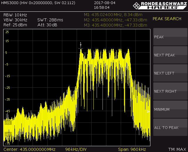
I always wanted antenna tracker. There are many commercial ones integrated to their OSD’s and transmitting location info back by audio channel or sometimes video. Not the way I wanted and pretty expensive.

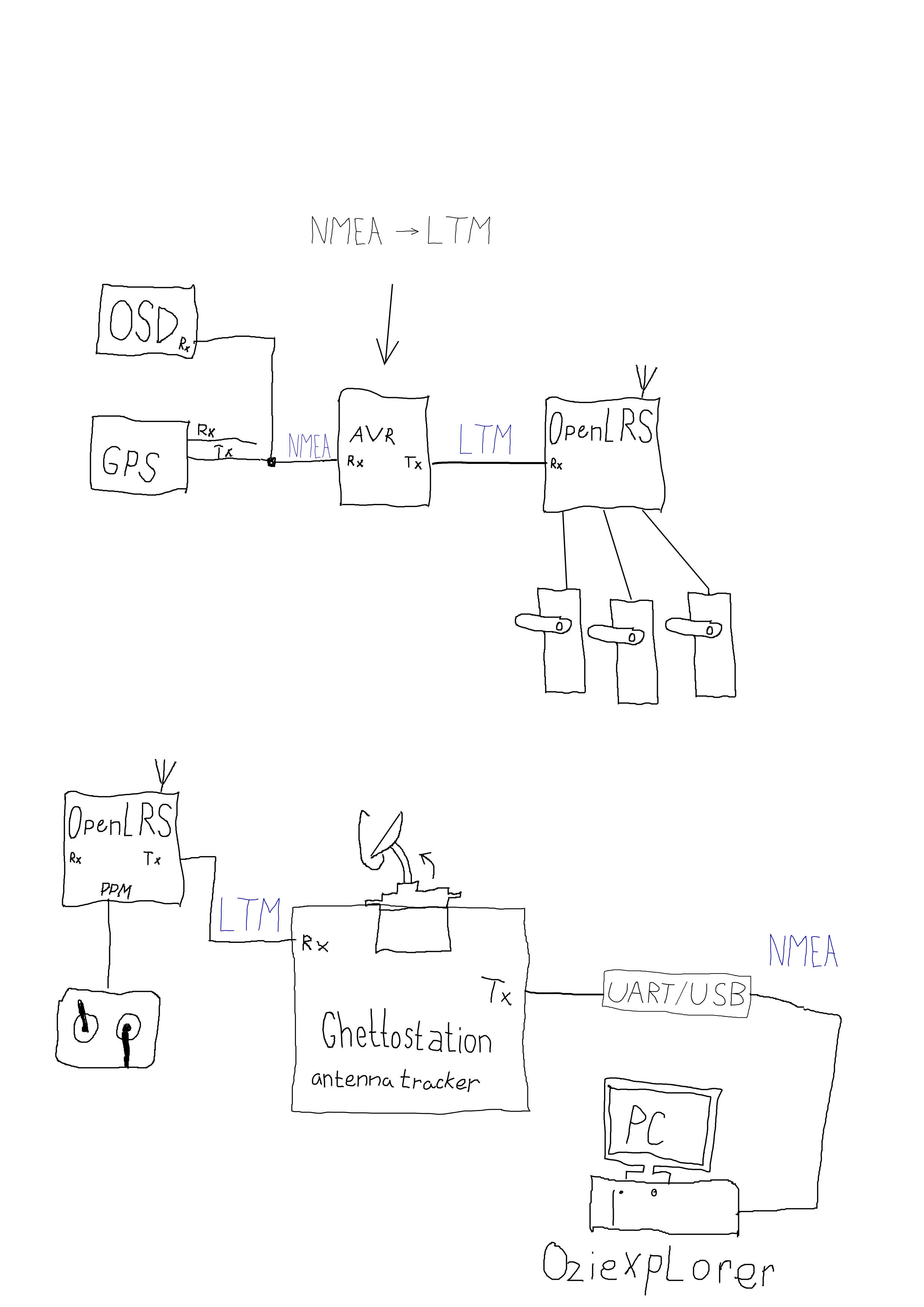
After switching to my version of OpenLRS I searched for antenna tracker project (source code) suitable for use with OpenLRSng’s transparent telemetry. Then I found Ghettostation by KipK. It is running on arduino, has display and buttons and is open source. I havent had Arduino Mega nor Teensy, so I modified source code to run on atmega328. For now I am running it on OpenLRS receiver without RF module. When my Teensy arrive, I will switch it.

Author’s website

Source code on GitHub

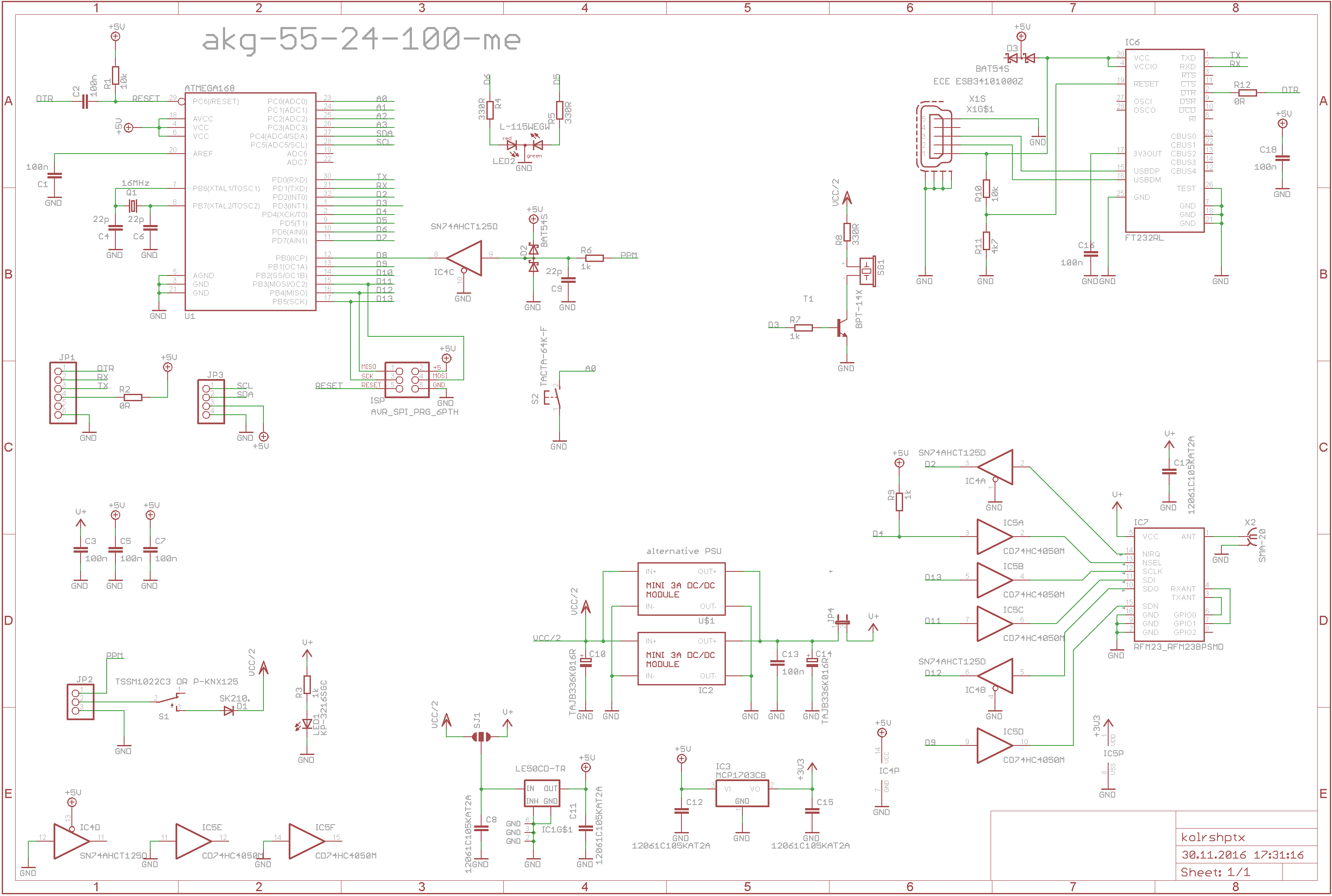
Simplified schematic:

ltmencoder

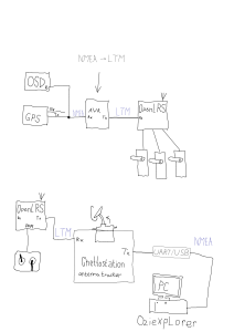
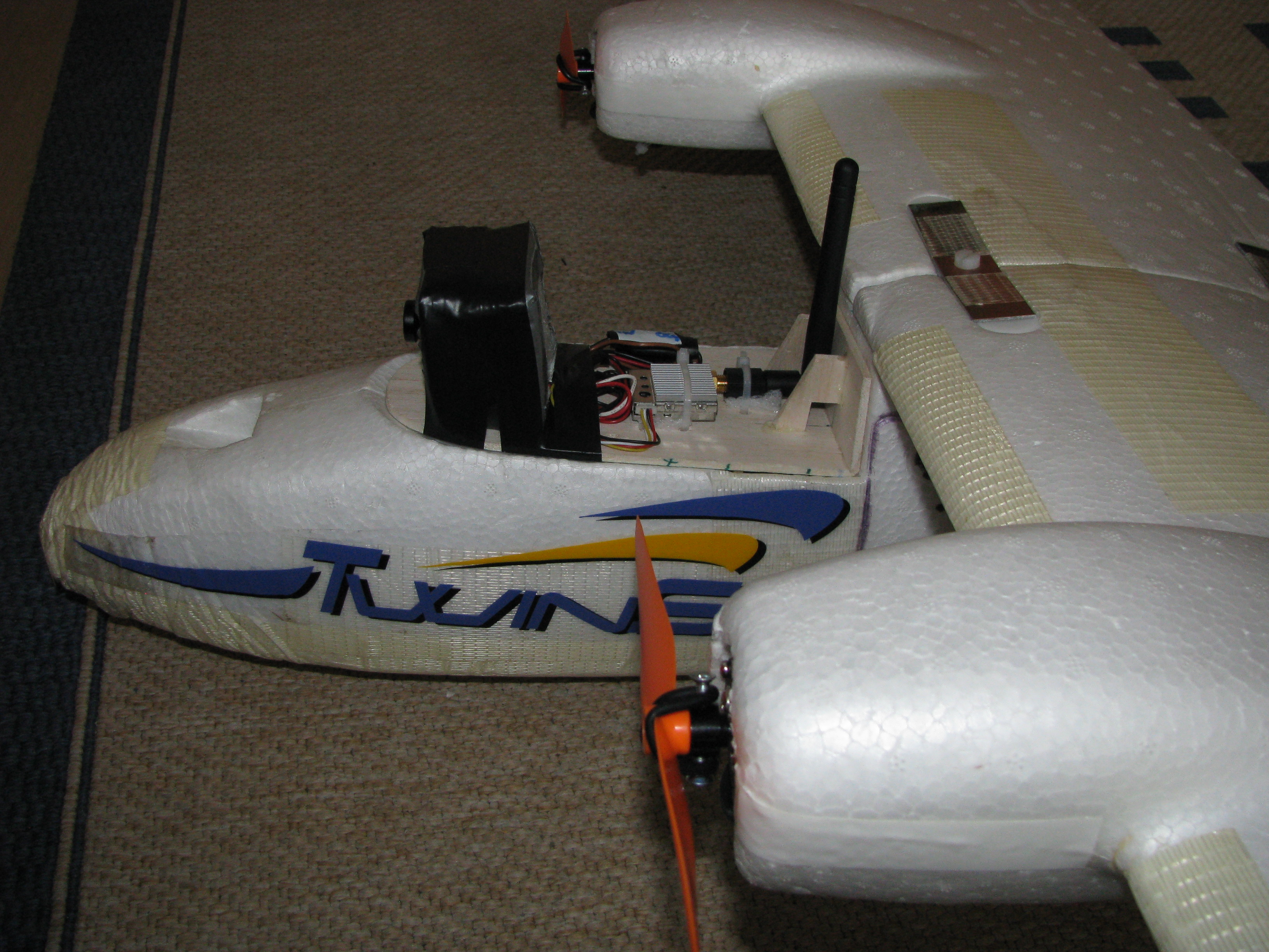
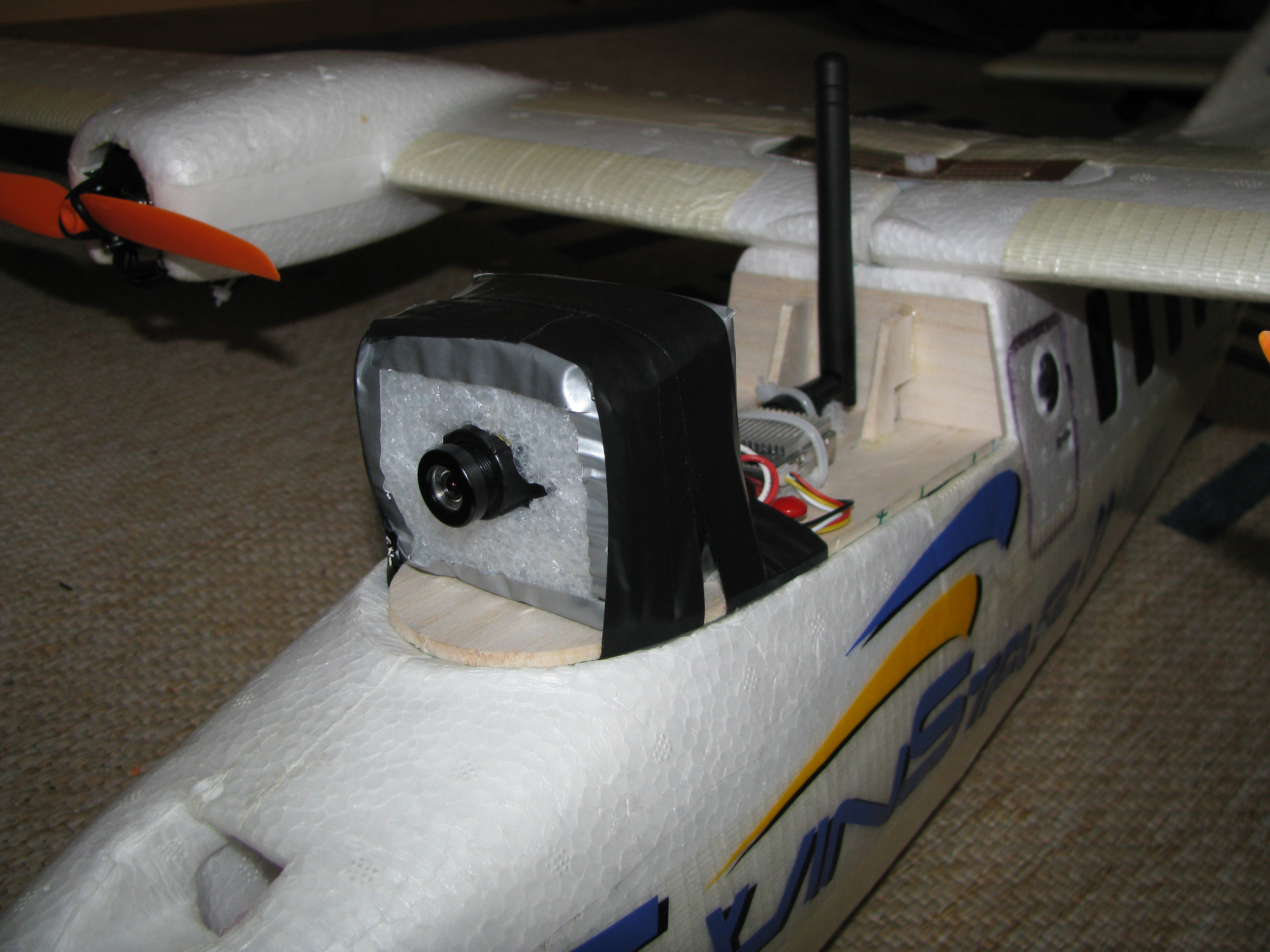
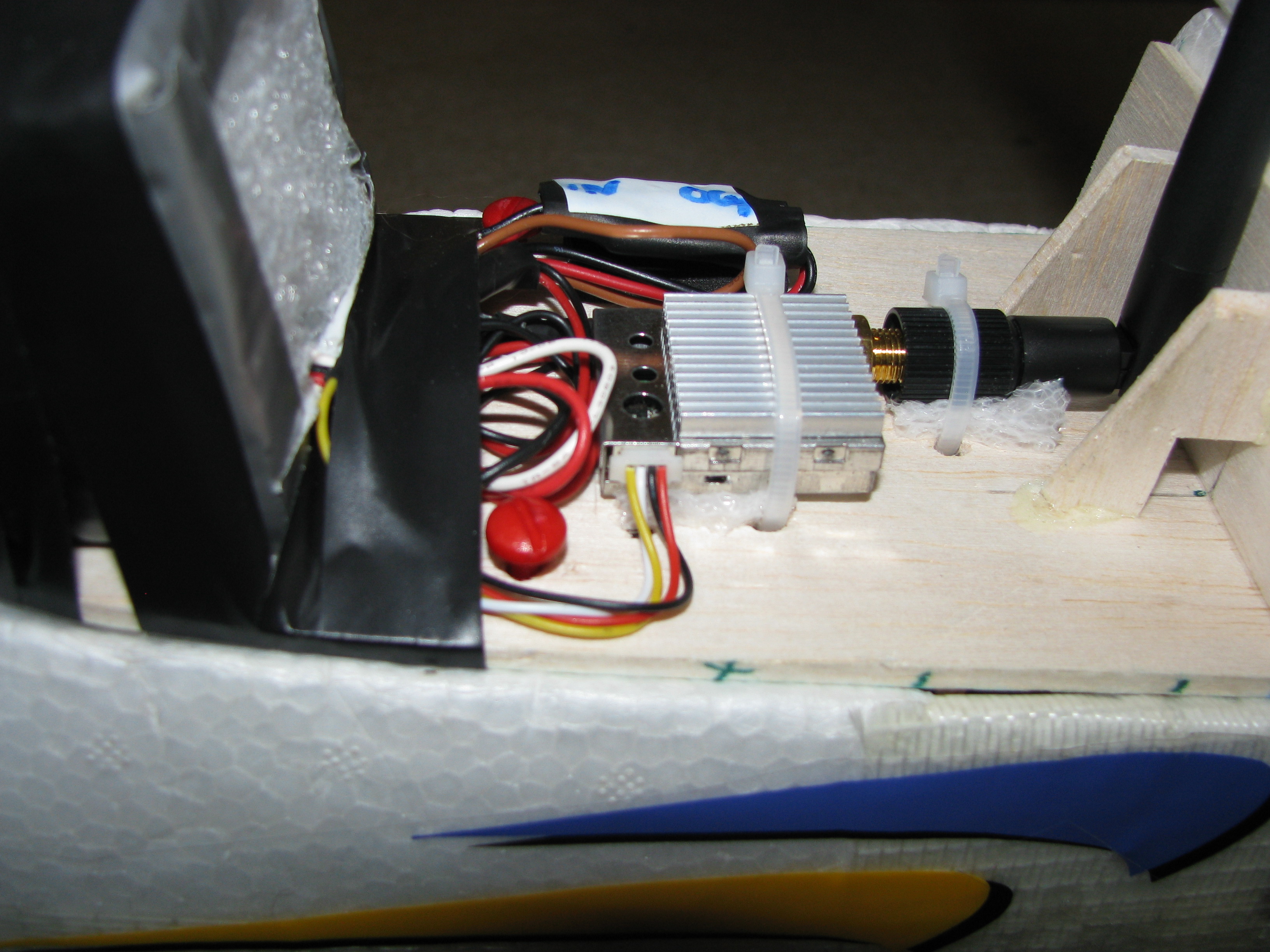
Ghettostation understands several protocols natively, like Mavlink or UAVtalk. This is great, but in some of my planes, there is no autopilot. Just GPS and OSD. Also, using Mavlink directly needs to have full featured serial telemetry to plane with XBEE or 3DR modems. To address this, GS has it’s own protocol called LightTelemetry (LTM). It is optimized for very low baudrate and one way communication only. This was meant to be used with FSK audio modems. But it is great for OpenLRSng as well! Kipk included support for LTM in TauLabs and Multiwii, so if you have one of these, load modified firmware and connect it with receiver and you are done.  But if you have other flight control or none, I made simple arduino program for parsing NMEA crap and encoding it in LTM packets. I used TinyGPS++ library for parsing NMEA and few lines from TauLabs code.

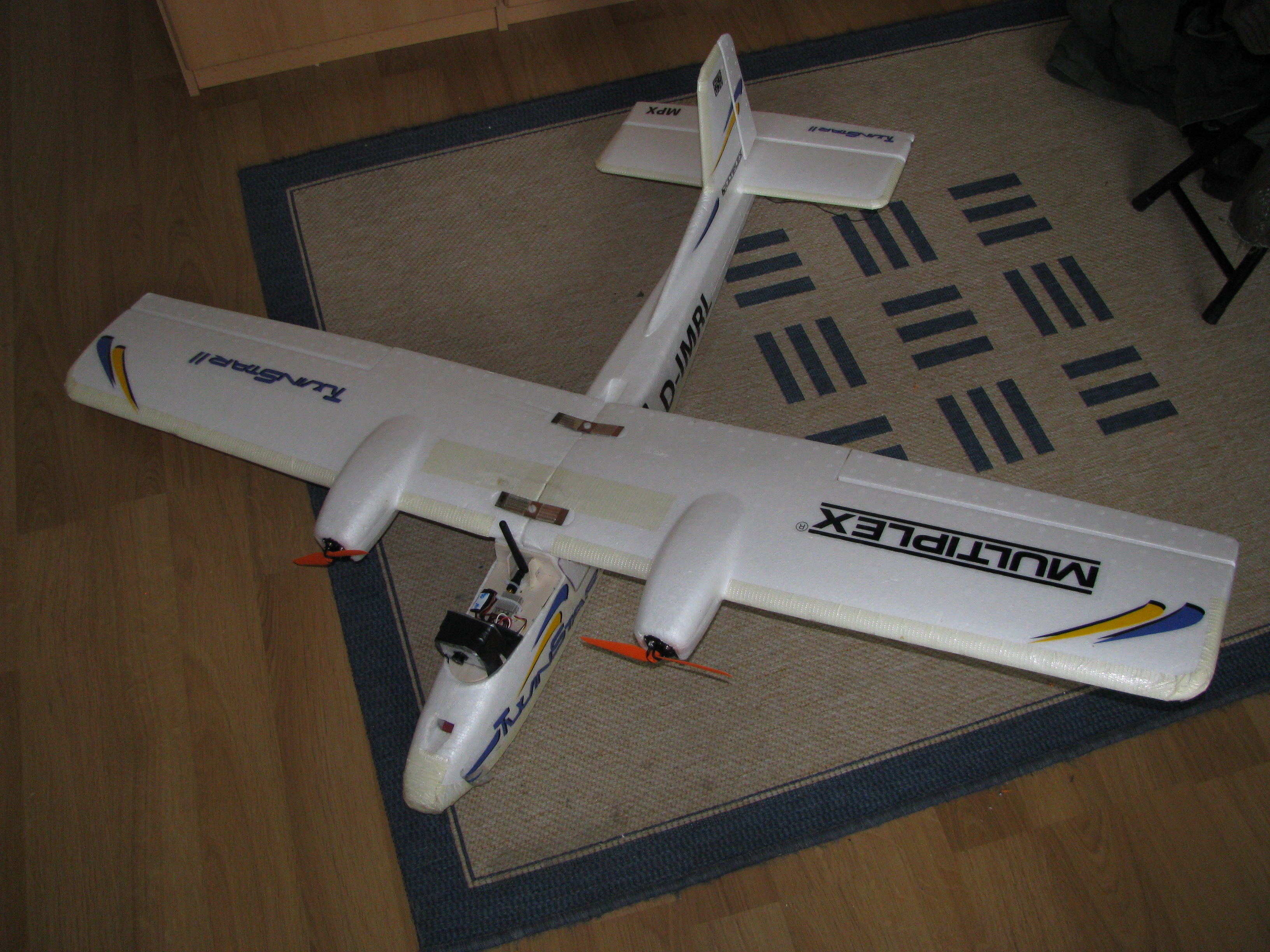
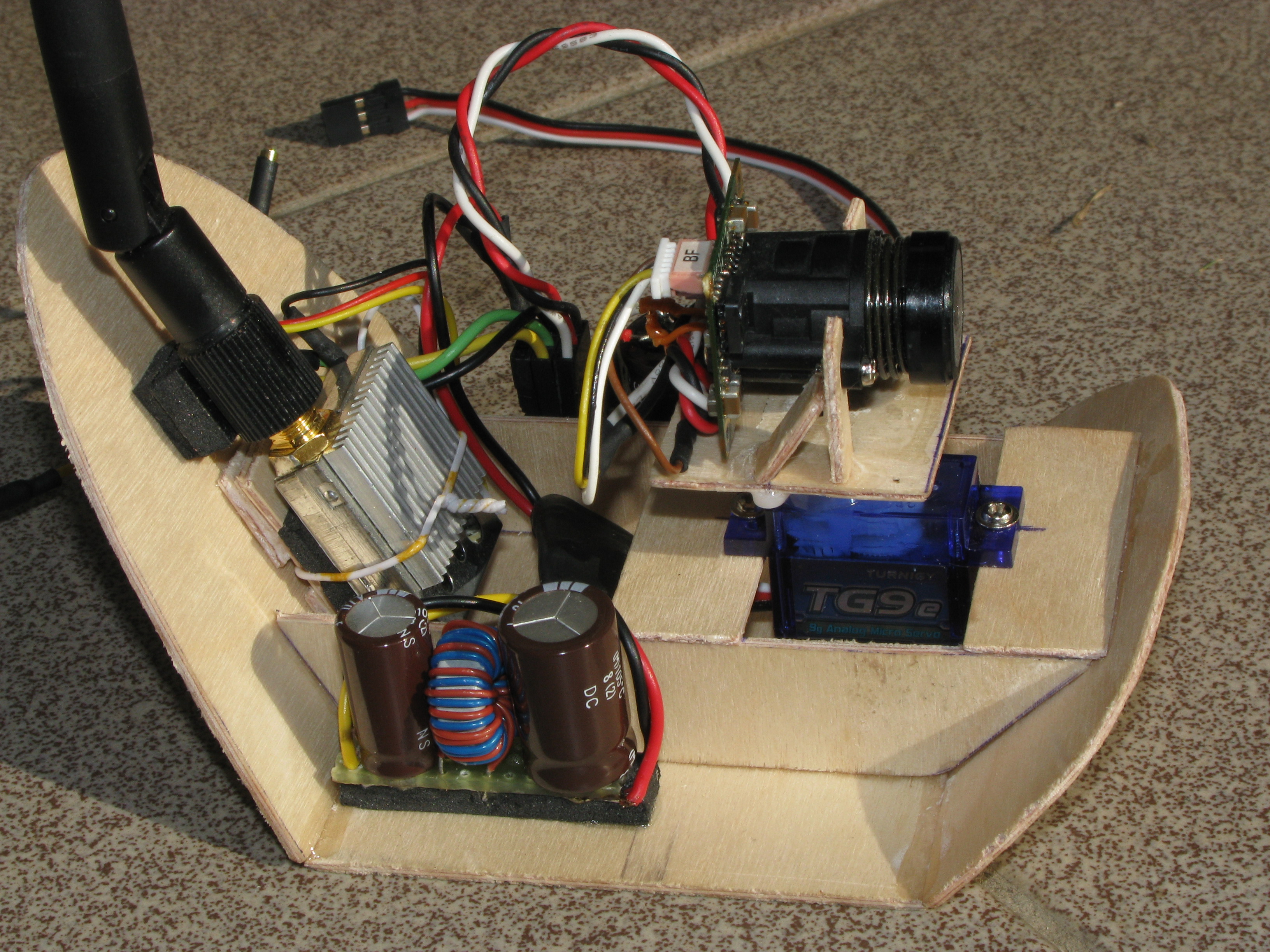
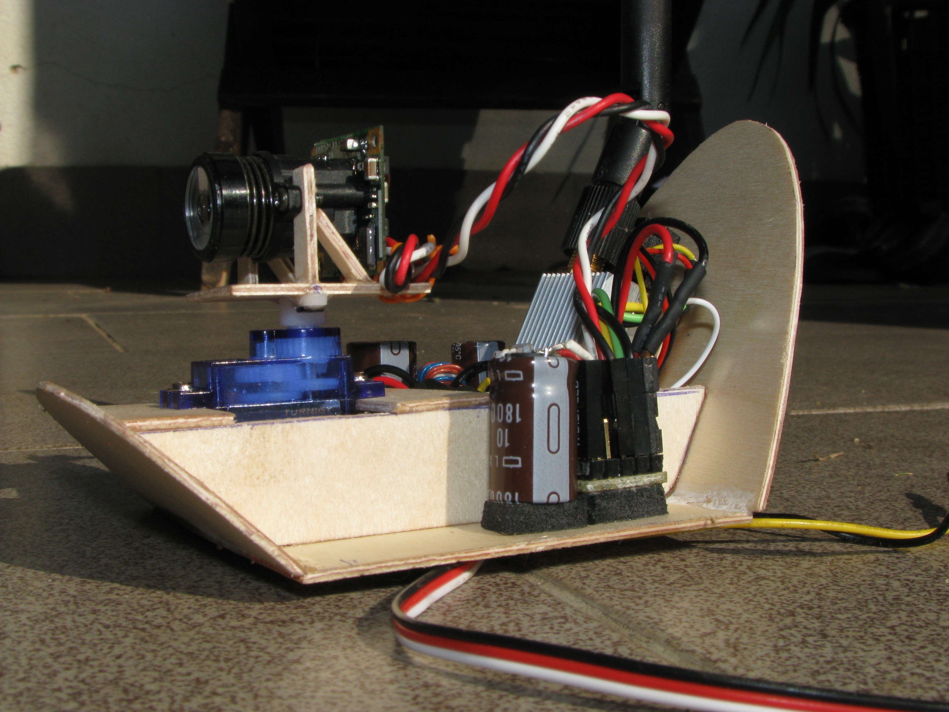
Antenna tracker hardware is still under development, I had to find a good way to do panning. I used what I had around and recycled most of the stuff. Pan servo is modified to 360 degreed by replacing potentiometer with external one geared from servo output.  Tilt servo is direct drive.

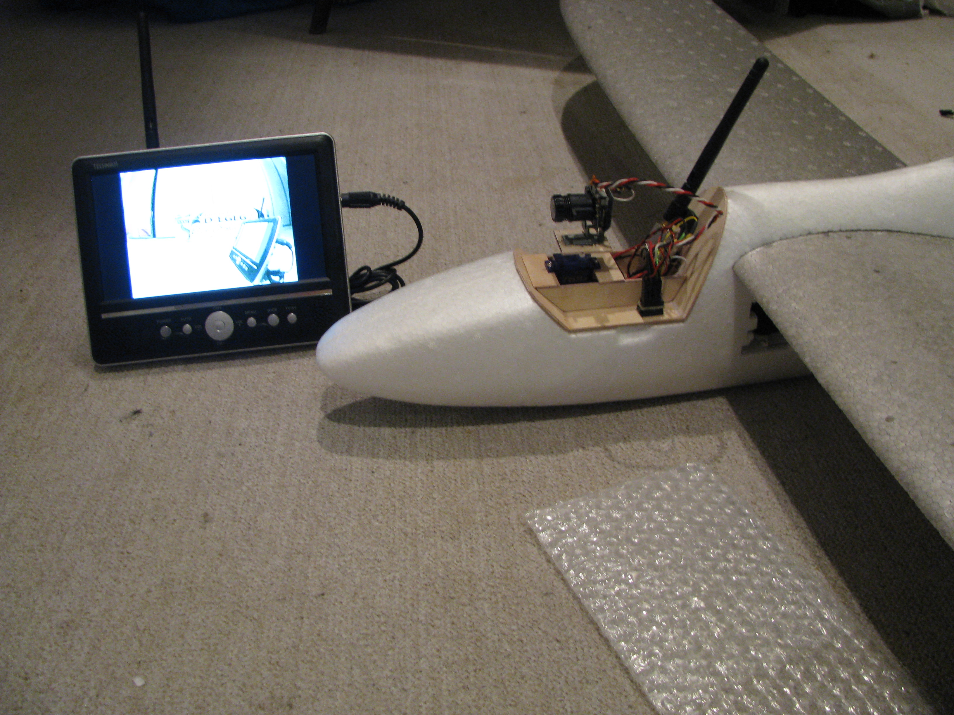
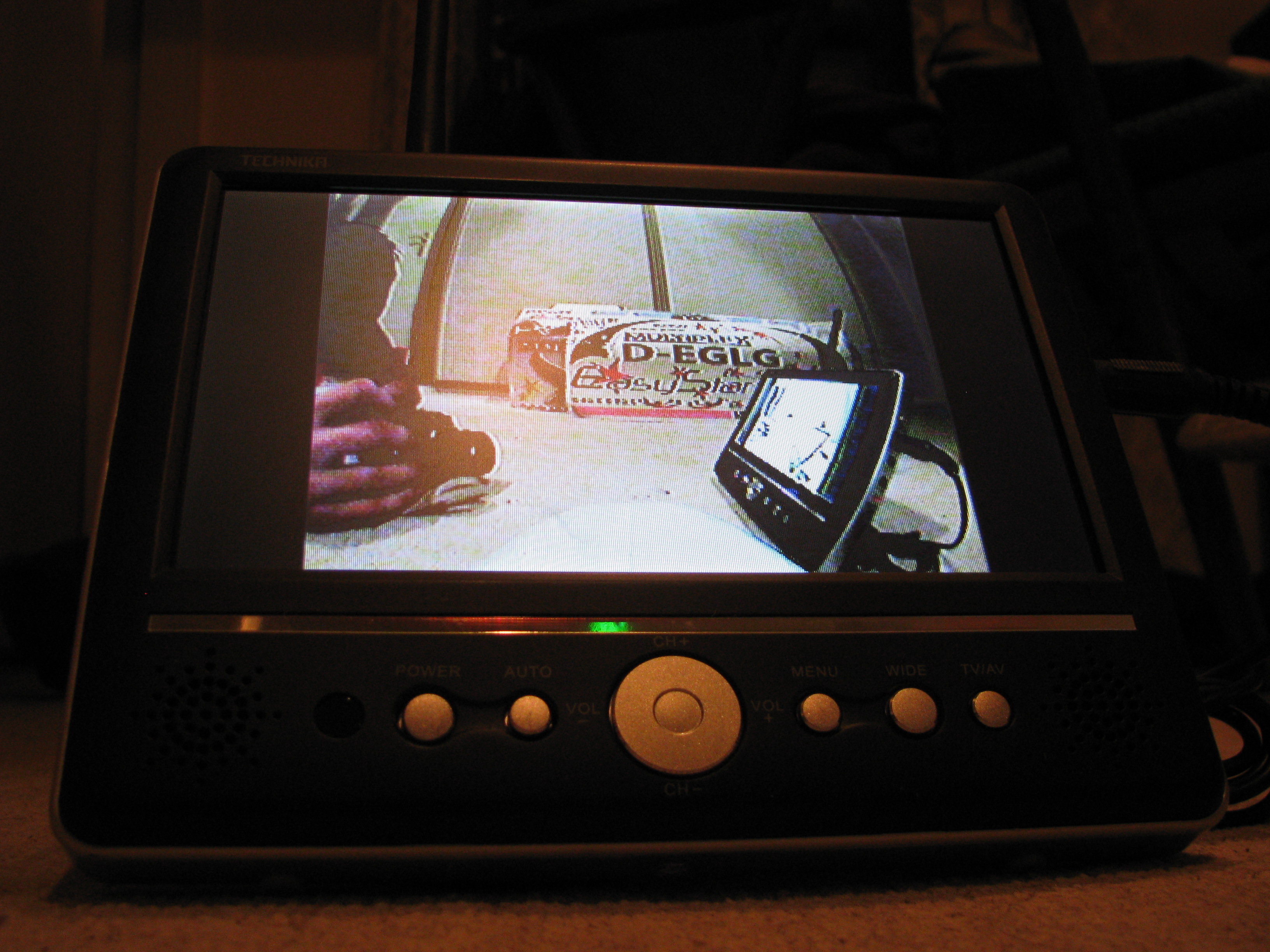
Today I made first field test, walking around with big breadboard and great wire mess. Whole setup worked, tracker was pointing at me all the time! There is still issue with pan servo precision and ancient Garmin GPS is not very accurate, but still big success for me.

Can’t wait to finish this and fly with tracker on regular basis.

As a future feature, my plan is to add piece of code into GS to reconstruct NMEA sentences from LTM to use Oziexplorer (or any other desktop map software – no google maps) on PC to see my plane on map.

IMG_0284IMG_0276

IMG_0282IMG_0288IMG_20140315_162743

Code for protocol translating Arduino:

[cpp]

/**
*****************************************************************************
* NMEA to LightTelemetry protocol translator, for use in UAV
* to be used with ghettostation https://code.google.com/p/ghettostation/
* requires TinyGPS++ library
*
* using only one serial port: GPS output to RX pin, TX pin to datalink input.
* GPS > LTM encoder > wireless datalink in air >>> wireless datalink on earth > ghettostation
* (c) kolin 2014
*****************************************************************************
*
* #################################################################################################################
* LightTelemetry protocol (LTM)
*
* Ghettostation one way telemetry protocol for really low bitrates (1200/2400 bauds).
*
* Protocol details: 3 different frames, little endian.
* G Frame (GPS position) (2hz @ 1200 bauds , 5hz >= 2400 bauds): 18BYTES
* 0x24 0x54 0x47 0xFF 0xFF 0xFF 0xFF 0xFF 0xFF 0xFF 0xFF 0xFF 0xFF 0xFF 0xFF 0xFF 0xFF 0xC0
* $ T G ——–LAT——– ——-LON——— SPD ——–ALT——– SAT/FIX CRC
*
* A Frame (Attitude) (5hz @ 1200bauds , 10hz >= 2400bauds): 10BYTES
* 0x24 0x54 0x41 0xFF 0xFF 0xFF 0xFF 0xFF 0xFF 0xC0
* $ T A –PITCH– –ROLL— -HEADING- CRC
*
* S Frame (Sensors) (2hz @ 1200bauds, 5hz >= 2400bauds): 11BYTES
* 0x24 0x54 0x53 0xFF 0xFF 0xFF 0xFF 0xFF 0xFF 0xFF 0xC0
* $ T S VBAT(mv) Current(ma) RSSI AIRSPEED ARM/FS/FMOD CRC
* #################################################################################################################
*/

#include <TinyGPS++.h>
#define BAUDRATE 4800
#define LTM_GFRAME_SIZE 18

TinyGPSPlus gps; //define TinyGPS++ object
TinyGPSCustom fixtype(gps, "GPGSA",2); //extract for fix type (no,2D,3D..) $GPGSA sentence, 2nd element

long previousMillis = 0;
long interval = 200; //5Hz telemetry send rate
bool newdata = false;

void setup()
{
Serial.begin(BAUDRATE);
}
void loop()
{
unsigned long currentMillis = millis();
if (Serial.available() > 0) //check serial line for new data
{
if (gps.encode(Serial.read())) //while feeding tinyGPS with new data, check if it has new sentence parsed
{
newdata=true;
}
}

if(currentMillis – previousMillis > interval && newdata == true) //do this part only in interval
{
previousMillis = currentMillis; // save the last time you passed
newdata=false;
uint8_t* LTM_Packet = encode_LTM_Packet(); //prepare the packet
Serial.write(LTM_Packet, LTM_GFRAME_SIZE); //send the packet
}

}

static uint8_t* encode_LTM_Packet()
{
int32_t lt_latitude = 10000000 * gps.location.lat(); //Latitude in degrees (double)
int32_t lt_longitude = 10000000 * gps.location.lng(); // Longitude in degrees (double)
uint8_t lt_groundspeed = (uint8_t) round(gps.speed.mps()); //Speed in meters per second (double)
int32_t lt_altitude = gps.altitude.value(); // Raw altitude in centimeters (i32)
uint8_t lt_gpssats = (uint8_t) round(gps.satellites.value()); // Number of satellites in use (u32)
uint8_t lt_gpsfix = atoi(fixtype.value()); //type of GPS fix, returns string, so the conversion

//code copied from TauLabs with LTM support
uint8_t LTBuff[LTM_GFRAME_SIZE];
//G Frame: $T(2 bytes)G(1byte)LAT(cm,4 bytes)LON(cm,4bytes)SPEED(m/s,1bytes)ALT(cm,4bytes)SATS(6bits)FIX(2bits)CRC(xor,1byte)
//START
LTBuff[0]=0x24; //$
LTBuff[1]=0x54; //T
//FRAMEID
LTBuff[2]=0x47; //G
//PAYLOAD
LTBuff[3]=(lt_latitude >> 8*0) & 0xFF;
LTBuff[4]=(lt_latitude >> 8*1) & 0xFF;
LTBuff[5]=(lt_latitude >> 8*2) & 0xFF;
LTBuff[6]=(lt_latitude >> 8*3) & 0xFF;
LTBuff[7]=(lt_longitude >> 8*0) & 0xFF;
LTBuff[8]=(lt_longitude >> 8*1) & 0xFF;
LTBuff[9]=(lt_longitude >> 8*2) & 0xFF;
LTBuff[10]=(lt_longitude >> 8*3) & 0xFF;
LTBuff[11]=(lt_groundspeed >> 8*0) & 0xFF;
LTBuff[12]=(lt_altitude >> 8*0) & 0xFF;
LTBuff[13]=(lt_altitude >> 8*1) & 0xFF;
LTBuff[14]=(lt_altitude >> 8*2) & 0xFF;
LTBuff[15]=(lt_altitude >> 8*3) & 0xFF;
LTBuff[16]= ((lt_gpssats << 2)& 0xFF ) | (lt_gpsfix & 0b00000011) ; // last 6 bits: sats number, first 2:fix type (0,1,2,3)
uint8_t LTCrc = 0x00;
for (int i = 3; i < LTM_GFRAME_SIZE-1; i++) {
LTCrc ^= LTBuff[i];
}
LTBuff[LTM_GFRAME_SIZE-1]=LTCrc;

return LTBuff;
}

[/cpp]


My FPV history, first steps

February 2010

I started with famous Twinstar II by Multiplex. Then first steps with Lawmate 2.4GHz/500mW, B/W CCD camera and laptop with USB digitzer. My first ever FPV flight ended really quick, my camera can not stand freezing temperatures and stopped working after few seconds.  FPV was put off for a while.

Old TS2 Old TS2 Old TS2 Old TS2


 July 2010

I crashed original TS2 too many times during LOS flying, I decided to buy Eaystar. I got new 480TVL camera, new 7″ portable TV, reused old Lawmate, RC on 35MHz.

ezstar1_2 ezstar1_3 ezstar1_6 ezstar1_8

With this setup I finally made some real FPV flights.  Max range was about 800m, then RC start to drop. This plane died in nose dive after failure of my transmitter (Hitec optic 6 sport). Luckily FPV pod was not there and only flying LOS.