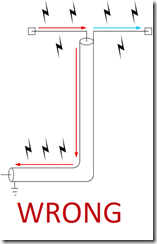
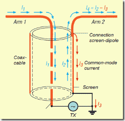
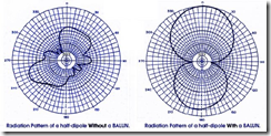
Most of the people are making dipole antennas wrong. Just connecting one pole to center of coax and the other to shield does make poor tri-pole with very distorted radiation pattern. Why tri-pole? Because outer side of shield of coax is carrying RF current and radiates while it should not. On third image you can see poor radiation pattern of dipole without balun.
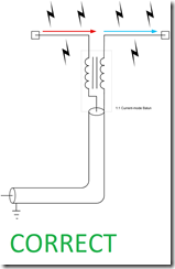
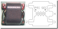
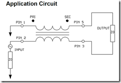
Solution? There are many solutions to solve this. Voltage mode balun, current mode balun, matched transmission line stubs and so on. But for FPV I like 1:1 current transformer design:
Luckily MACOM ETC1-1-13 is exact part we need. It is small SMD part, cheap and easy to get on Aliexpress or eBay. It is rated for max 250mW and up to 3GHz.
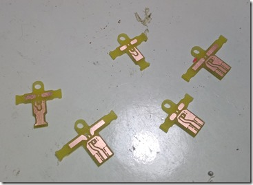
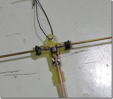
With this information in mind, I have drawn very simple PCB design and milled it on CNC router. Not really knowing if I want it for solder-on SMA connector or direct coax attachment I have designed both and some variations of mechanics. Antennas can be made to any frequency needed, just use longer or shorter poles.
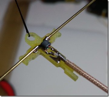
Solder poles and coax
Wrap poles together with PCB by strong sewing thread and wick with thin CA. Super strong and poles should not broke off.
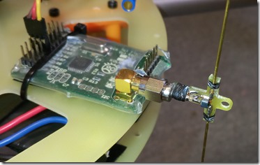
Another method is to solder SMA made for RG-174 directly instead of coax. Wrapping method applies to SMA too.
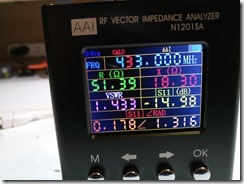
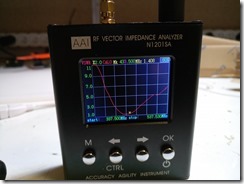
When everything is soldered and fixed, tuning begins. Put antenna on analyzer and cut off poles by few mm at time on both sides. Frequency starts to shift high and when it is where you want stop cutting. That’s it. SWR 1.4 at 433MHz is what is expected. Dipole is naturally 73ohm plus some reactance, and this type of balun is does not match impedance. It just stops common mode current. So mismatch from 75ohm to 50ohm is still there. But it can be neglected.
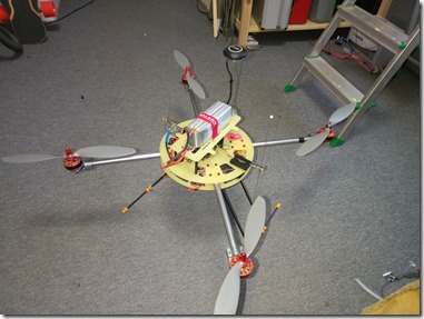
And finally this is ready for first flight on my old school test rig. Right is 433MHz for telemetry radio and left is 868MHz for OpenLRSng
Eagle files and DXF for milling of antenna cores will be released in few days.
